5.8. Video with Vulkan on Android
Simul’s Android client supports the decoding of video streams through the use of the Android NDK AMedia and AImage libraries. See Video Decoding with Android NDK. We currently require the support of these two Vulkan device extensions:
VK_KHR_sampler_ycbcr_conversion (https://registry.khronos.org/vulkan/specs/1.3-extensions/man/html/VK_KHR_sampler_ycbcr_conversion.html).
VK_ANDROID_external_memory_android_hardware_buffer (https://registry.khronos.org/vulkan/specs/1.3-extensions/man/html/VK_ANDROID_external_memory_android_hardware_buffer.html).
When available from Khronos, that and suitable drivers and runtimes are available from the device vendors, we should optionally support:
VK_KHR_video_queue (https://registry.khronos.org/vulkan/specs/1.3-extensions/html/chap50.html#VK_KHR_video_queue)
VK_KHR_video_decode_queue (https://registry.khronos.org/vulkan/specs/1.3-extensions/html/chap50.html#VK_KHR_video_decode_queue)
VK_KHR_video_decode_h264 (https://registry.khronos.org/vulkan/specs/1.3-extensions/html/chap50.html#VK_EXT_video_encode_h264)
VK_KHR_video_decode_h265 (https://registry.khronos.org/vulkan/specs/1.3-extensions/html/chap50.html#VK_EXT_video_encode_h265)
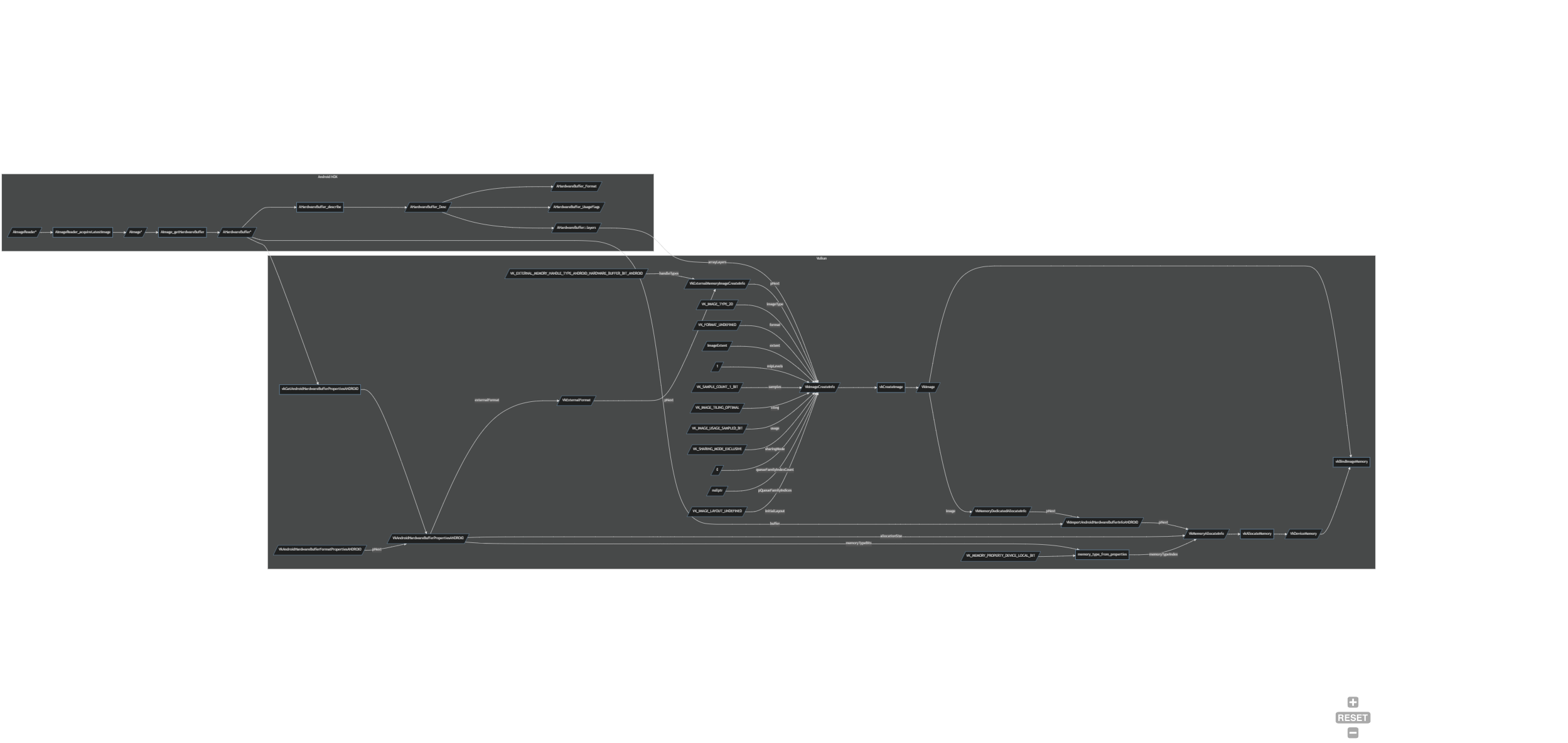
5.8.1. Importing a Video Stream into Vulkan
Simul’s Android client has class teleport::android::NdkVideoDecoder that interfaces with class teleport::android::VideoDecoderBackend, which extends class avs::DecoderBackendInterface. The NdkVideoDecoder sets up a AMediaCodec Decoder and AImageListener, from which an AImage and its AHardwareBuffer can be obtained. The AHardwareBuffer is obtained from the AImage by calling AImage_getHardwareBuffer(); and a AHardwareBuffer_Desc can also be obtained by calling AHardwareBuffer_describe(). From this point the class NdkVideoDecoder uses the VK_ANDROID_external_memory_android_hardware_buffer extension to import the memory held by the AHardwareBuffer into Vulkan.
The following is brief description on how this is implemented:
We call
vkGetAndroidHardwareBufferPropertiesANDROID()filling out the chained structures:VkAndroidHardwareBufferPropertiesANDROIDandVkAndroidHardwareBufferFormatPropertiesANDROID.From
VkAndroidHardwareBufferFormatPropertiesANDROID::externalFormat, the device/vendors specific format can be obtained.We fill out a
VkExternalFormatANDROIDstructure usingVkAndroidHardwareBufferFormatPropertiesANDROID::externalFormat. TheVkExternalFormatANDROIDstructure is chained into aVkExternalMemoryImageCreateInfostructure, and we bitwise setVkExternalMemoryImageCreateInfo::handleTypesto includeVK_EXTERNAL_MEMORY_HANDLE_TYPE_ANDROID_HARDWARE_BUFFER_BIT_ANDROID.We fill out a
VkImageCreateInfostructure chaining in theVkExternalMemoryImageCreateInfostructure. The Vulkan specification requires theVkImageCreateInfostructure to be set up as follows:VkImageCreateInfo::flagsto0.VkImageCreateInfo::imageTypetoVK_IMAGE_TYPE_2D.VkImageCreateInfo::formattoVK_FORMAT_UNDEFINED(This defined in theVkExternalFormatANDROIDstructure).VkImageCreateInfo::extentequal to that of the image size specified in theAMediaCodec.VkImageCreateInfo::mipLevelsto1.VkImageCreateInfo::arrayLayersequal to that ofAHardwareBuffer_Desc::layers.VkImageCreateInfo::samplestoVK_SAMPLE_COUNT_1_BIT.VkImageCreateInfo::tilingtoVK_IMAGE_TILING_OPTIMAL.VkImageCreateInfo::usagetoVK_IMAGE_USAGE_SAMPLED_BIT.VkImageCreateInfo::sharingModetoVK_SHARING_MODE_EXCLUSIVE.VkImageCreateInfo::queueFamilyIndexCountto0.VkImageCreateInfo::pQueueFamilyIndicestonullptr.VkImageCreateInfo::initialLayouttoVK_IMAGE_LAYOUT_UNDEFINED.
We call
vkCreateImage().We fill out a
VkMemoryDedicatedAllocateInfostructure settingVkMemoryDedicatedAllocateInfo::imageto theVkImagecreated previously. Vulkan requires thatVkImage``s that are to be backed by an ``AHardwareBufferbe a dedicated allocation. We fill out aVkImportAndroidHardwareBufferInfoANDROIDstructure chaining in the previousVkMemoryDedicatedAllocateInfostructure and settingVkImportAndroidHardwareBufferInfoANDROID::bufferto theAHardwareBufferobtained from theAMediaCodec’sAImageoutput.We fill out a
VkMemoryAllocateInfostructure chaining in theVkMemoryDedicatedAllocateInfostructure. We setVkMemoryAllocateInfo::allocationSizeequal to theVkAndroidHardwareBufferPropertiesANDROID::allocationSize.We use
VkAndroidHardwareBufferPropertiesANDROID::memoryTypeBitsto select a Memory Type Index for Vulkan to use, and we set that index value intoVkMemoryAllocateInfo::memoryTypeIndex. We also ensure that the selected Memory Type has theVK_MEMORY_PROPERTY_DEVICE_LOCAL_BITassociated with it.We call
vkAllocateMemory(). Depending on the device vendor’s implementation of the Vulkan specification in its runtime, the implementation will at worse copy the contents of theAHardwareBufferto a different memory location valid for use in Vulkan, or at best map the memory address to the createdVkDeviceMemory.We call
vkBindImageMemory()backing theVkImagewith theVkDeviceMemory, which is itself ‘backed’ by theAHardwareBuffer.We store the
VkImageandVkDeviceMemoryfor later use and deletion.
Flow chart:
5.8.2. Vulkan Sampler YCbCr Conversion
Simul’s Rendering library Platform (https://github.com/simul/Platform/tree/dev) supports the use of YCbCr samplers for Vulkan.
5.8.2.1. YCbCr Colour Space
YCbCr is favoured over RGB for video broadcasting and streaming as the format implicitly compresses the video data, saving on bandwidth. YCbCr is based on the YUV standard for broadcast television, wherein the video signal is split into a luma (Y) and two chroma (Cb/Cr) components. It is vital to remember that the chroma components are defined to be the difference between the original colour and the luma signal, and therefore the chroma components are signed values ranging from -0.5 to 0.5, whereas the luma component ranges from 0.0 to 1.0, in a signed normalised co-ordinate space.
Reference: Wikipedia YCbCr.
5.8.2.2. Chroma Subsampling
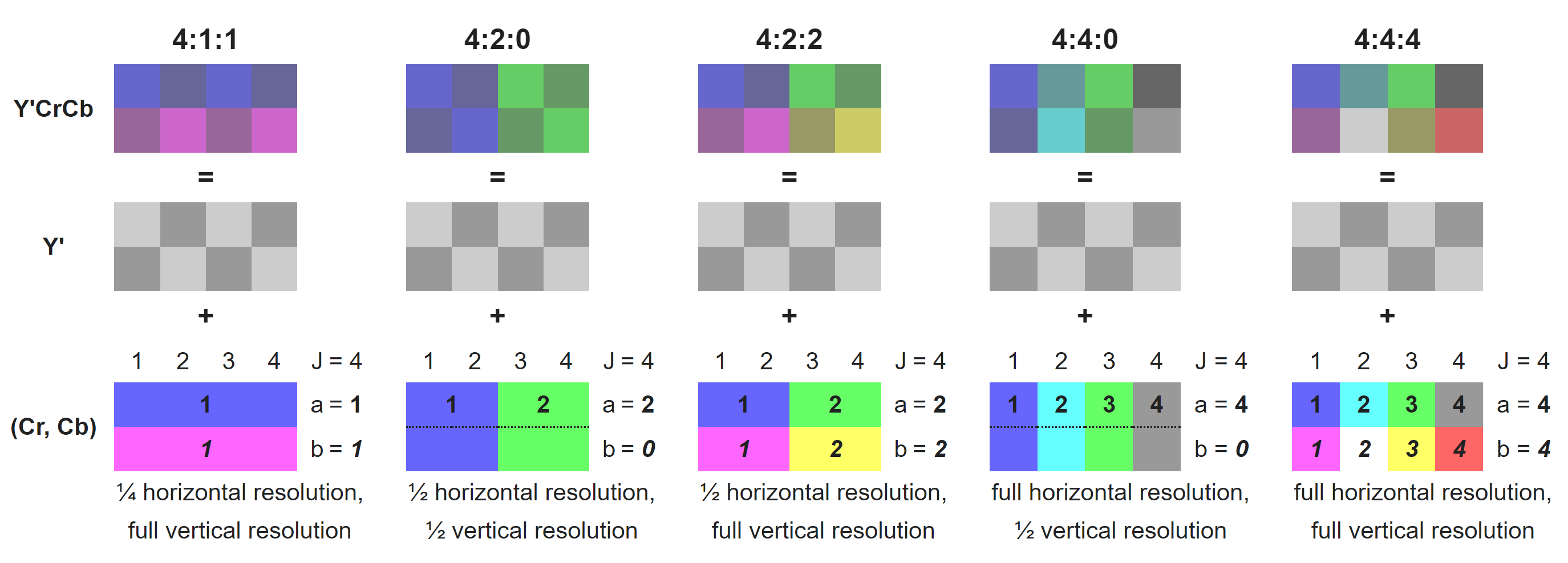
Further compression of the video data can be achieved by downsampling the chroma components without affecting the colour perspection. This is because the human eye is less sensitive to high frequency changes in colour data. Chroma Subsampling is expressed by three-part ratio J:a:b, such as 4:2:2.
J: horizontal sampling reference (width of the conceptual region). Usually, 4.
a: number of chrominance samples (Cb, Cr) in the first row of J pixels.
b: number of changes of chrominance samples (Cb, Cr) between first and second row of J pixels.
5.8.2.3. Interleaved, Planar and Semi Planar
This qualifier refers to the how the data is organised in memory.
An Interleaved layout means that the luma and chroma components are interleaved onto a single plane.
A Planar layout means that the luma and the two chroma components each have their own planes.
A Semi Planar layout means that the luma component has its own plane, and the chroma components are interleaved onto their single plane.
Type / Plane |
0 |
1 |
2 |
|---|---|---|---|
Interleaved |
YUV |
||
Planar |
Y |
U |
V |
Semi Planar |
Y |
UV |
4:2:2 |
||
|---|---|---|
UYVY |
Interleaved |
U0 Y0 V0 Y1 U1 Y2 V1 Y3 U2 Y4 V2 Y5 U3 Y6 V3 Y7 |
YUY2 |
Interleaved |
Y0 U0 Y1 V0 Y2 U1 Y3 V1 Y4 U2 Y5 V2 Y6 U3 Y7 V3 |
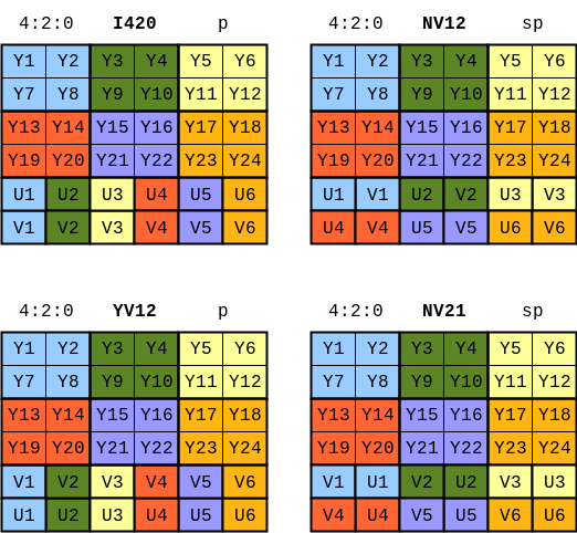
4:2:0 |
||
|---|---|---|
I420 |
Planar |
Y1 Y2 Y3 Y4 Y5 Y6 Y7 Y8 U1 U2 V1 V2 |
YV12 |
Planar |
Y1 Y2 Y3 Y4 Y5 Y6 Y7 Y8 V1 V2 U1 U2 |
NV12 |
Semi Planar |
Y1 Y2 Y3 Y4 Y5 Y6 Y7 Y8 U1 V1 U2 V2 |
NV21 |
Semi Planar |
Y1 Y2 Y3 Y4 Y5 Y6 Y7 Y8 V1 U1 V2 U2 |
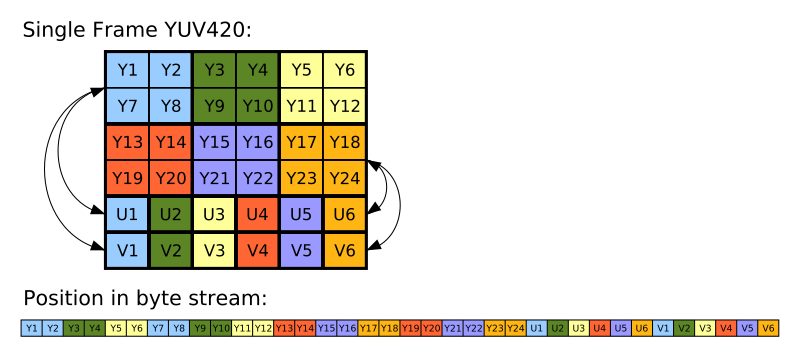
Reference: Video LAN Wiki YUV.
Reference: About YUV formats.
Reference: Wikipedia Y′UV420p (and Y′V12 or YV12) to RGB888 conversion.
5.8.2.4. ITU Colour Spaces and Encoding Ranges
As YCbCr is the digital version of the analogue television standard YUV, the ITU (International Telecommunication Union) has defined both the colour spaces and the quantisations the three colour space standards.
The primaries below can be used to create a 3 x 3 matrix that can convert to and from RGB to YCbCr colour spaces. The primaries in the table below are just the luma (Y) component of these colour standards based in the CIE xyY colour space. See reference: Wikipedia CIE 1931 color space: CIE xy chromaticity diagram and the CIE xyY color space.
In terms of the encoding range, the ITU reserved regions at the beginning and end of each ‘representable integer range for rounding errors and for signal control data’. These reversed regions mean that the video data has a narrow range encoding, and their absence means that the video source has full range encoding. Currently, only BT.2100 requires full range encoding: All others use the narrow range encoding.
ITU Standard |
TV Format |
Red Primary |
Green Primary |
Blue Primary |
BT.601 |
SD |
0.299 |
0.587 |
0.114 |
BT.709 |
HD |
0.2126 |
0.7152 |
0.0722 |
BT.2020 |
UHD |
0.2627 |
0.6780 |
0.0593 |
      float3x3 YCbCrToRGB_ConversionMatrix(uint type)
      {
              float a, b, c, d, e;
              switch (type)
              {
                      case 0:
                      {
                              a = Colour_BT601_PrimaryR.z;
                              b = Colour_BT601_PrimaryG.z;
                              c = Colour_BT601_PrimaryB.z;
                              break;
                      }
                      default:
                      case 1:
                      {
                              a = Colour_BT709_PrimaryR.z;
                              b = Colour_BT709_PrimaryG.z;
                              c = Colour_BT709_PrimaryB.z;
                              break;
                      }
                      case 2:
                      {
                              a = Colour_BT2020_PrimaryR.z;
                              b = Colour_BT2020_PrimaryG.z;
                              c = Colour_BT2020_PrimaryB.z;
                              break;
                      }
              }
              d = 2 * (a + b);
              e = 2 * (1 - a);

              return float3x3(
                      float3(1.0,                0.0,                  e),
                      float3(1.0, (-1.0 * c * d / b), (-1.0 * a * e / b)),
                      float3(1.0,                  d,                0.0)
              );
      }

      {
              float3 Y1CbCr;
              float3 RGB = mul(Y1CbCr, YCbCrToRGB_ConversionMatrix_Fast(type));
      }
Reference: Khronos Colour Space Conversions
Reference: Khronos Colour Space Quantisation
5.8.2.5. Co-sited vs Midpoint
Due to the downsampling of the chroma components, when loading a YCbCr image for use in a shader, it is required that the full chroma samples are reconstructed from the lower spatial resolution of the chrominance planes. The two offset methods are Co-sited and Midpoint. Figures 5 - 10 in Section 16.3.8. of the Vulkan Specification show how the rescaled chroma plane(s) are overlayed on top of the luma plane for 4:2:2 and 4:2:0 in all varying combinations of Co-sited and Midpoint for X and Y. The downsampling method used on the server must match the upsampling method used on the Android client for the chrominance data to be reconstructed accurately.
Reference: Khronos Chroma Reconstruction
5.8.2.6. Simul’s Implementation
Simul’s Implementation uses 4:2:0 NV12 Semi Planar, BT.709.
On Meta Quest and Meta Quest 2, the AMediaCodec selects a vendor specific format OMX_QCOM_COLOR_FormatYUV420PackedSemiPlanar32m. This is Khronos OpenMax Qualcomm extension that is specific to Qualcomm SoCs (System On Chip) such as the Snapdragon 835/Adreno 540 (Meta Quest) and the Qualcomm Snapdragon XR2/Adreno 650 (Meta Quest 2).
We create a VKSamplerYcbcrConversionKHR from a VkSamplerYcbcrConversionCreateInfoKHR. The majority of the memebers of the structure can filled out using the VkAndroidHardwareBufferFormatPropertiesANDROID structure acquired earlier. Here again VkSamplerYcbcrConversionCreateInfoKHR::format is set to VK_FORMAT_UNDEFINED as the format is defined in the chained VkExternalFormatANDROID structure. VkComponentMapping is set to VK_COMPONENT_SWIZZLE_IDENTITY for the R, G, B and A values. The component remapping is useful for when the Cb and Cr components are swapped such as the NV21 memory layout for 4:2:0. For VkSamplerYcbcrConversionCreateInfoKHR::chromaFilter we use VK_FILTER_NEAREST so as not to ‘blend’ between the chrominance pixels, and we disable VkSamplerYcbcrConversionCreateInfoKHR::forceExplicitReconstruction.
With the VKSamplerYcbcrConversionKHR created, we assign this to VkSamplerYcbcrConversionInfoKHR::conversion and chain the VkSamplerYcbcrConversionInfoKHR structure into a VkSamplerCreateInfo structure for platform::vulkan::RenderPlatform’s single video sampler and into a VkImageViewCreateInfo structure for each instance of platform::vulkan::Texture where a YCbCr conversion is needed.
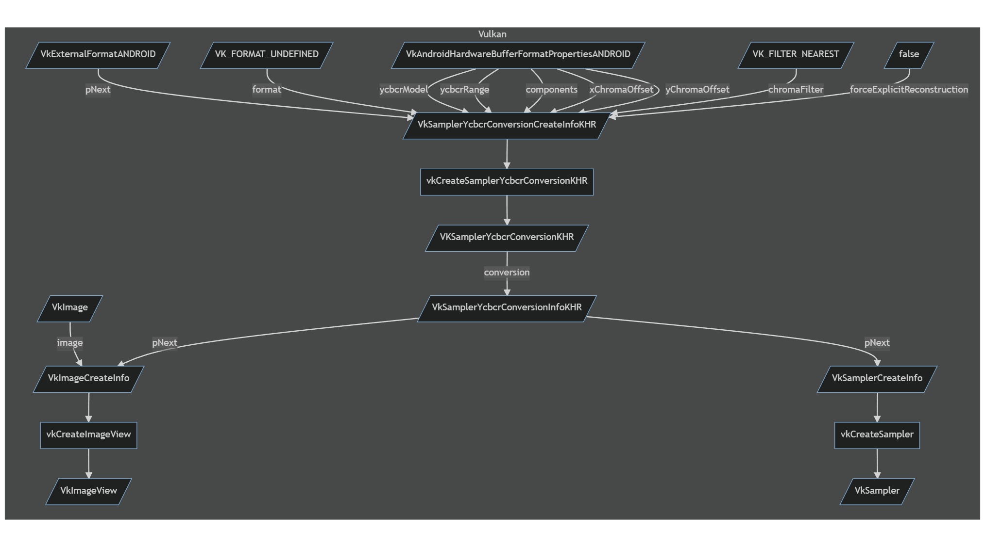
5.8.2.7. YCbCr in Compute Shaders and Load Operations
Presently, the video sampler is unused, as we do a HLSL: Texture2D.Load() / GLSL: texelFetch() operation in a compute shader. The previous information used to create VKSamplerYcbcrConversionKHR, and that was ultimately passed to the VkImageView, is still used to reconstruct the chrominance data, returning the separated Y, U and V components as if it were a 4:4:4 Planar YCbCr image. The load operation converts the 8-bit unsigned integer (0 - 255) to a normalised floating point 32-bit value (0.0 - 1.0). This works fine for the luma component, but the chroma need to offset by -0.5, putting them in the range (-0.5 - 0.5) to match the YCbCr colour space. The load operation assigns the Y, Cb and Cb channels to the RGB channels as follows:
Y => G.
U => B.
V => R.
      Texture2D<float4> ycbcrTexture;
      RWTexture2D<float4> rgbTexture;

      float3x3 YCbCrToRGB_ConversionMatrix_Fast(uint type)
      {
              float3x3 result;
              switch (type)
              {

                      case 0:
                      {
                              result = float3x3(
                                      float3(+1.000, +0.000, +1.402),
                                      float3(+1.000, -0.344, -0.714),
                                      float3(+1.000, +1.772, +0.000));
                              break;
                      }
                      default:
                      case 1:
                      {
                              result = float3x3(
                                      float3(+1.0000, +0.0000, +1.5748),
                                      float3(+1.0000, -0.1873, -0.4681),
                                      float3(+1.0000, +1.8556, +0.0000));
                              break;
                      }
                      case 2:
                      {
                              result = float3x3(
                                      float3(+1.0000, +0.0000, +1.4746),
                                      float3(+1.0000, -0.1646, -0.5714),
                                      float3(+1.0000, +1.8814, +0.0000));
                              break;
                      }
              }
              return result;
      }

      void CS_ConvertYCbCrToRGB(uint3 position, uint type)
      {
              float3 value = ycbcrTexture.Load(int3(position.x, position.y, 0)).rgb;
              float Cr = value.r - 0.5;
              float Cb = value.b - 0.5;
              float Y1 = value.g;

              vec4 clr;
              clr.rgb = mul(float3(Y1, Cb, Cr), YCbCrToRGB_ConversionMatrix_Fast(type));
              clr.a = 1.0;
              rgbTexture[position.xy] = clr;
      }

      [numthreads(8, 8, 1)]
      shader void CS_ConvertYCbCrToRGB_BT709(uint3 position : SV_DispatchThreadID)
      {
              CS_ConvertYCbCrToRGB(position, 1);
      }
5.8.2.8. Classes
teleport::android::NdkVideoDecoder teleport::android::VideoDecoderBackend
See also avs::DecoderBackendInterface.